Before going to understand Zener diode characteristics, we should know basics like semiconductor, diode, and PN-Junction Diode.
Table of Contents
What is Diode?
Diode, is a two terminal semiconductor component that allows current flow in just one direction and opposes in other direction.
What is a PN-Junction Diode?
PN-junction diode, is a basic semiconductor device formed by connecting p-type and n-type semiconductor materials. It lets current flow in one direction and blocks it in the other, which makes it useful for controlling electrical signals.
Zener diode
A Zener diode is a two terminal heavily doped PN-junction diode, also known as breakdown diode. In forward biased It can behaves as same as that of PN-junction diode. In reverse bias breakdown of voltage occurs. It is specially designed to work in reverse bias condition.
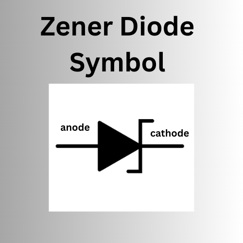
Zener diode symbol

Zener diode characteristics
The Voltage-Current (V-I) characteristics of a Zener diode describe how it behaves with different voltages.
Forward Bias
When you apply a positive voltage to the anode, the Zener diode acts like a regular diode. That allowing current to flow easily with a small voltage drop, usually around 0.7V.
Reverse Bias
In reverse bias condition, Zener diode blocks current up to a certain voltage. At one particular Zener breakdown voltage, there is sudden current flow in diode. The diode starts conducting in the reverse direction. Once this breakdown voltage is reached, keeps the voltage across it almost constant.
Breakdown Region
After the Zener voltage is reached, the current sharply increases without changing the voltage. The region where voltage constant with increase in current flow , is called as Breakdown region. In this region diode can be used as a Voltage Regulator.
Table of Zener diode characteristics
| Characteristics | Description |
|---|---|
| Zener Voltage | The voltage at which the diode starts conduction in reverse. |
| Breakdown Voltage | The voltage at which the diode allows current to flow in reverse due to Zener effect. |
| Forward Voltage (V) | The voltage drop across the diode when it’s forward-biased, typically around 0.7V. |
| Reverse Leakage Current | A small current that flows when the diode is reverse-biased but not breakdown mode. |
| Dynamic Resistance (Rz) | The resistance of the diode in the breakdown region, which helps maintain stable voltage. |
| Temperature Coefficient | How much the Zener voltage changes with temperature, usually given in mV/°C |
| Power Dissipation (Pz) | The maximum power the diode can handle without overheating or damage. |
| Zener Impedance (Zz) | The impedance in the breakdown region, affecting its voltage regulation performance. |
These are the main features that affect how a Zener diode performs in circuits.
Zener diode as a voltage regulator
The main application of the Zener Diode is Voltage Regulator.
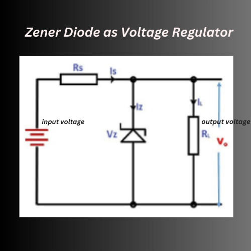
Circuit Diagram

How It Works?
In the circuit, the Zener diode is connected in reverse bias condition across the load. When the reverse voltage reaches the Zener breakdown voltage, the diode starts conduction. The diode maintains a constant voltage across it. The Zener diode keeps the output voltage stable by allowing excess voltage to drop across itself.
As the input voltage varies, the voltage across the load remains constant. A resistor is always placed in series with the Zener diode. Because to limit the current flowing through the diode and to drop the excess voltage. This resistor helps protect the diode and adjust the current to the desired level.
Characteristics
- Regulation Voltage: The Zener diode maintains constant Zener voltage, which is the output voltage of the regulator.
- Load Regulation: The load changes will not affect the Zener voltage. A well-chosen Zener diode and resistor combination can minimize variations.
- Line Regulation: stable output voltage despite variations in the input voltage.
- Simplicity: This method is simple and inexpensive.
- Current Limiting: The series resistor ensures that the current through the Zener diode stays within safe limits, preventing damage.
Applications
- Used to regulate voltage for small electronic devices.
- Provides a precise voltage reference for other components in a circuit.
- Helps in protecting circuits from over-voltage conditions by clamping the voltage to a required level.
